About the Development Team
In the Spring 2023 semester, Boeing Experimental Flight’s Development Team has two major deliverables:
- The development of a new wing design that will be used in test flights
- The generation of a detailed model of the truss-braced wing design developed by the aircraft performance team
The development team consists of team lead Ryan Rouleau with members Dominic Chong Sheng Lim, Joseph Hanley, Alejandro Sanchez, Zachary Hollenbeck, and Ayan Asim.
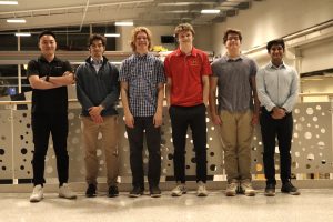
Left to Right: Dominic Chong Sheng Lim, Joseph Hanley, Alejandro Sanchez, Ryan Rouleau (team lead), Zachary Hollenbeck, Ayan Asim
Update 4/14:
Adapter Fabrication
With the CAD model of the wing-to-fuselage adapter complete, fabrication began by submitting 3D print jobs to the M2I. The 3D printers at the lab did not have a large enough plate to print the entire adapter as one piece. This resulted in the adapter model being split into two pieces, the front and back half. Pegs were added to the front half, with holes added to the back half for a seamless adapter connection after the 3D print. The adapter underwent a total of 2 test prints for the front portion of the adapter and 3 test prints for the back half of the adapter. The first reprint was of the entire adapter, as it was too small for the current hole in the AL-37 fuselage. After the reprint, the adapter fits tightly within the fuselage and had a nice fit, as shown in the figure below.
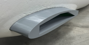
Test Print 2 of Adapter
With the update to the size of the total adapter, the front and back half had to be reworked to fix the alignment and tolerance of the holes for the wires, wing support rod, and connection tabs. After this reprint, the adapter fits great and properly integrated the wing, as shown below.

Adapter Integrated with Test Wing
The final rework for the adapter was specifically on the back half, where the landing gear must be integrated. Given that we had the prefabricated fuselage and landing gear, the team had to carefully consider integrating the landing gear into our adapter. The team updated the CAD model, submitted the print, and finally finished the adapter.

Wing Side View of Final Adapter

Fuselage Side View of Adapter
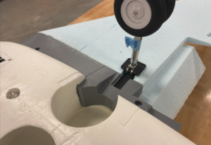
Landing Gear Integrated with Adapter
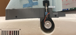
Landing Gear in Up Position
Wing Fabrication
As the adapter was being fabricated, the team also dove into learning how to fabricate a fully operational wing. This encompassed an enormous amount of testing and learning. Team members worked with servos, control surfaces, mechanisms to connect the servos and control surfaces, integrating wires through the wing, adding structural support, and more.
After testing on old wings and spare materials in the M2I lab, the fabrication of the final wing began by working with the resource at Iowa State University to CNC a wing from our cad model. The CNC machine cut out the base wing and the accompanying control surfaces.
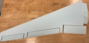
Test wing with control surfaces (unattached)
The team then began integrating the servos by 3D printing control horns. Below is the mechanism that is used to operate the control surfaces.
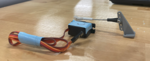
Control Horns Integrated to a Servo
Another part of the development of the wing was adding spars throughout the wing to increase its structural strength. The carbon fiber rods were integrated into the wing by channeling out a wing section with handheld rods. The rods were then glued into place, and scrap foam was used to backfill the holes. In addition, the handheld hot wire cutter was used to channel out slots for the servos, nacelle, and wires.
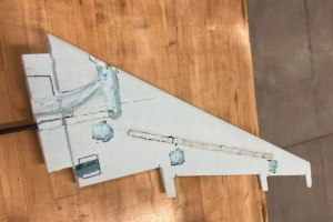
Final Wing with Support Rods, Servo Slots, Nacelle Slot, and Wire Channel
The team then began a rough assembly of the wing to test the control surfaces, landing gear, and overall connection to the wing.
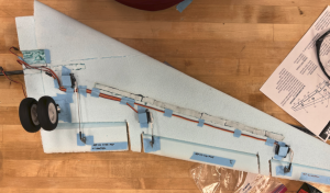
Test Assembly of the Final Wing
Future Plans
The development team has nearly completed the left wing of the aircraft. The team will finish adding composite and monokote layers to finish the left wing. Moving forward, the team will perform the same manufacturing process for the right wing, and it is scheduled to be completed by Friday, April 21st. Currently, the team is waiting for the shipment of monokote and control surface hinges. As these items are out of our hands, the team has begun working on the Truss Braced CAD model to gain experience with the process. When wing manufacturing is complete, the team will dive further into CAD and develop a detailed CAD model from the parameters provided by the performance team.
Team Reflection
Overall Boeing Experimental Development Team has made great progress this semester. The team faced many challenges and overcame them despite having a new team lead and various new members. The team quickly picked up on the new wing’s design using previous semesters research, CAD models, and Star CCM+ data. The team continued Star CCM+ analysis to dive deeper into wing specifications like dihedrals, incidence angles, and control surfaces. At the same time, team members developed their CAD skills to design an adapter that seamlessly integrated a new wing into a professionally prefabricated fuselage. The team learned the importance of developing CAD models for fabrication by 3D prints and CNC machines.
As the team began to assemble the wing and integrate the servos, landing gear, nacelle, and wires, the team realized all the small details that go into fabrication. The team learned the importance of communicating to prepare for changes and noted the importance of planning ahead to stay on track. Although the team fell a little behind, and the wings will be provided a week later than expected, many valuable lessons were learned on working professionally to achieve engineering goals.
Earlier in the semester:
In order to develop the new wing, the Development team will finalize the configuration of the NACA 3513-3510 wing design using Star CCM+. The configuration includes identifying optimal dihedral and incidence angles. After choosing the optimal wing configuration, the team will design and fabricate an adapter that seamlessly integrates the current AL37 fuselage to the new NACA 3513-3510 wing configuration. Once the adapter design is completed, the team will begin its fabrication. While the adapter is being fabricated, the team will dive deeper into the process of wing fabrication. The Development Team will focus on items such as developing control surfaces, servo integration for the control surfaces, structural support, and engine integration. Once the adapter is fabricated, the entire team will be hands on fabricating the final NACA 3513-3510 wing that will be used in test flights.
CAD Designs
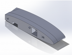
Front isometric view of adapter
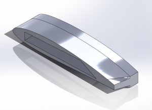
Back isometric view of adapter
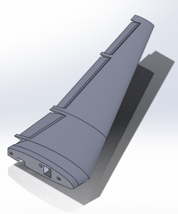
Complete NACA 3513-3510 Wing
Future Plans
After the wing is completed, the Aircraft Performance Team will begin a variety of test flights. The Aircraft Performance Team will also provide detailed information regarding a truss-braced wing design that the Development Team will utilize to make a truss-braced CAD model fit to integrate with the AL37 fuselage. This will set the foundation of performance computational fluid dynamics (CFD) analysis on the truss-based design in the semester of Fall 2023.
Past Semesters
Fall 2022
September Update:
The development Team will develop a new set of wings this semester. The first step toward this goal was determining airfoils for further Computational Fluid Dynamics (CFD) Analysis. The team researched a variety of airfoils in XFLR5 in September and determined six airfoils to test in Star-CCM: The NACA airfoils 1412, 2211, 3510, 4413, and 6410, as well as the Clark-Y. The end of September and beginning of October will be dedicated to utilizing the AL-37 CAD model from last semester to gather lift, drag, and moment data from Star-CCM. The team will then decide the most optimal airfoil for manufacturing.
The team will then enter its rapid prototyping phase. The team will manufacture blue foam wings of the selected airfoil to test connection systems to the AL37 fuselage. The team will also experiment with carbon fiber spar placement to determine the ideal structural setup of the wing.
Development Schedule (tentative):
-October 1st-31st: Selection of the airfoil, rapid prototyping of blue foam wings of the selected airfoil
-November 1st-30th: Begin manufacturing of final wing, prototyping, and finalizing AL-37-to-selected-airfoil adapter
-December 1st-January 30th (Spring semester), Conduct final assembly of the wing, post-process
November Update:
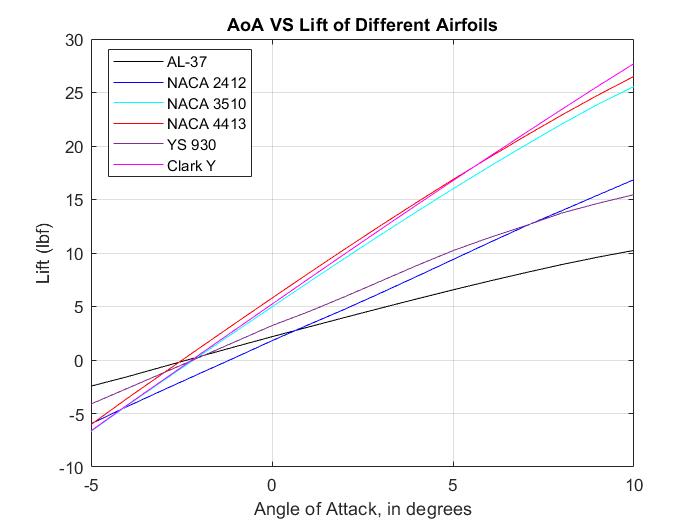
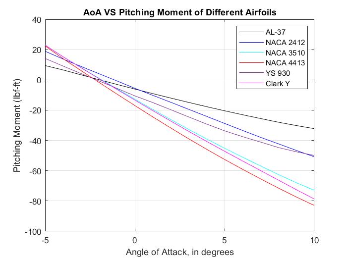
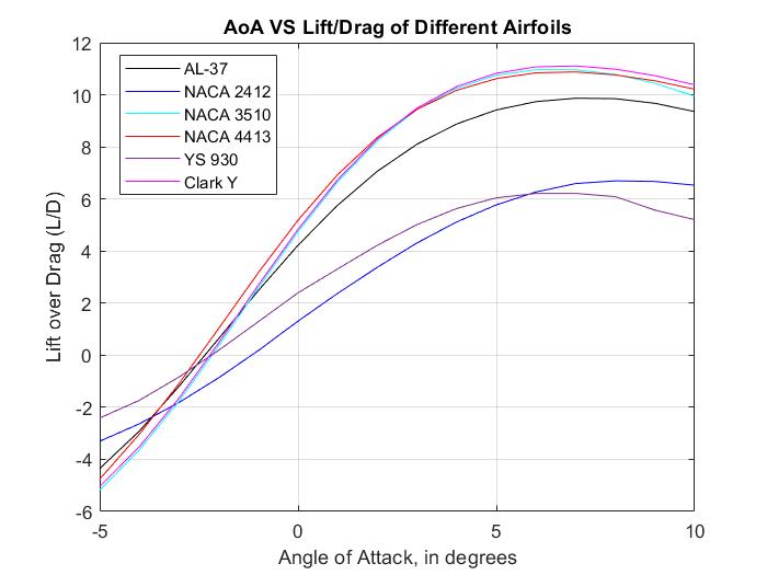
The development team conducted CFD of the aforementioned airfoils, as well as the NACA 2412 and the YS-930 from last semester, and compared results. The NACA 1412 and NACA 2211 were found to be unstable after CFD testing and were thus removed from further analysis. The NACA 6410 was found to have erratic results and was removed as well. The remaining airfoils were compared in MATLAB. Shown below from the top graph to the bottom graph, the angle of attack ranging from -5 to 10 degrees was plotted versus lift (lbf), pitching moment (lbf-ft), and the ratio of lift divided by drag. The NACA 3510, NACA 4413, and Clark Y were found to have the highest lift and lift over drag but also produced the largest pitching moments.
The YS-930 and NACA 4413 were found to be overwhelmingly stable, with a static margin of 53.1% and 54.0%, respectively. A desirable static margin is between 5% and 25%. The NACA 2412 was shown to give a static margin of 3.71%, which is also outside the range. For these reasons, those three airfoils were removed from consideration, leaving the NACA 3510 and Clark Y airfoils. The Clark Y gave slightly better results but is more difficult to manufacture as it is a non-NACA airfoil, whereas the NACA 3510 can be easily modified with airfoil tools and is built in into other programs, such as XFLR5. The team determined that the NACA 3510 would be ideal with these aspects in mind. Prototypes of the NACA 3510 were then manufactured, and are shown below.
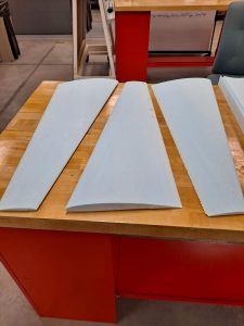
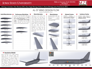
The team will use one wing for testing control surface placement and one wing for rigidity testing, with the third wing as a backup. The wings were found to be smaller in thickness than originally expected, and a new version of the prototypes is currently in manufacturing, while one wing was layed up with fiberglass. The team in the meantime compiled a full report of the CFD analysis process and the results gotten from it, which will be displayed at the Symposium. The first version of the report is also uploaded below.
Moving forward, the team will continue to work with the NACA 3510 wing and finish assembly by the end of January and move into work on the next truss-braced wing utilizing the airfoil.
Star_CCM_Analysis_Report